
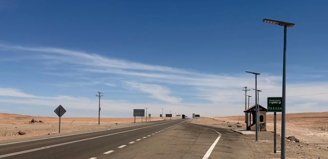
A solar street light is a tall pole with a flat plate on top. That plate is the best wind catcher on the road, and it sits at the end of the longest lever the structure has. Every quotation for one says something about wind — "designed for 45 m/s", "wind resistance grade 12", "certified to EN 40" — and almost none of those lines can be compared with each other, because they are quoting three different quantities.
This page separates them. It starts with the number on the datasheet, turns it into a pressure, turns the pressure into a bending moment at the base, and checks that moment against a real pole section. The arithmetic is short enough to redo on a calculator, which is the point: it lets you test a supplier's wind claim before the poles are on a ship.
Ask a supplier what wind speed their pole takes, and the answer is usually the basic wind velocity of a code — the speed a weather station might report. That is not the load on the pole, for two reasons.
The first is terrain. A pole standing in open desert or on a coastal road sees far more wind at 6 m than the same pole inside a town, where buildings and trees break the flow. Design codes handle this with an exposure factor that can double the pressure without changing the wind speed by a single metre per second.
The second is gust duration. A "40 m/s" figure means one thing if it is a ten-minute average and something else entirely if it is a three-second gust. Europe's EN 1991-1-4 uses the ten-minute mean. American ASCE 7 uses the three-second gust. The two are not interchangeable, and a datasheet that quotes one while your specification requires the other has told you nothing you can check.
| What it is called | What it measures | Typical source | What it is not |
|---|---|---|---|
| Basic wind velocity, vb | Wind at 10 m over open ground, 50-year return | National wind map or annex | Not the pressure on your pole |
| Peak velocity pressure, qp(z) | Pressure at the actual mounting height, after terrain and gust factors | Calculated from vb | Not the force, and not the capacity |
| Pole capacity | Bending moment the section, base plate and foundation can carry | EN 40-3-3 calculation or EN 40-3-2 test | Not a wind speed, unless someone converted it back |
A supplier who writes "45 m/s" without saying which row of that table they mean has given you a number that cannot be checked. The rest of this page shows what it takes to check one.
The conversion is one line of arithmetic. Air density is taken as 1.25 kg/m³ at sea level and 15 °C, which is the value EN 1991-1-4 uses by default.
qb = ½ × ρ × vb² with ρ = 1.25 kg/m³At 30 m/s that gives 563 Pa. At 42 m/s it gives 1,103 Pa — twice the pressure for 40% more speed. This is why "we upgraded from 35 to 42" is not a small change on a pole: it is 44% more bending moment at the base, and the pole either has the section for it or it does not.
The pressure at the luminaire is higher than qb, because the wind at 6 m has been slowed less by the ground than the wind at 10 m in the reference condition. EN 1991-1-4 expresses this as a peak velocity pressure, qp(z) = ce(z) × qb, where ce(z) combines terrain roughness and turbulence. For the two terrain cases that matter on a road project, the numbers look like this.
| Basic velocity vb | qb (open ground) | qp at 6 m, open terrain | qp at 6 m, town or village |
|---|---|---|---|
| 27 m/s | 0.46 kPa | 0.93 kPa | 0.39 kPa |
| 33 m/s | 0.68 kPa | 1.39 kPa | 0.59 kPa |
| 38 m/s | 0.90 kPa | 1.84 kPa | 0.78 kPa |
| 42 m/s | 1.10 kPa | 2.25 kPa | 0.95 kPa |
| 45 m/s | 1.27 kPa | 2.58 kPa | 1.10 kPa |
Read the first and last column of the 42 m/s row together: the same wind speed produces 2.25 kPa on an open road and 0.95 kPa inside a village. A factor of 2.4, from terrain alone. This is the single most common reason a product that has served a European town for a decade bends its first winter on a highway in Atacama.
Take a typical all-in-one unit: 6 m mounting height, a head with a 0.55 m² projected area including the panel, drag coefficient 1.2 for a flat plate at the worst orientation, on a tapered steel pole 140 mm at the base and 60 mm at the top with a 3 mm wall.
Design case: vb = 42 m/s, open terrain
qp(6 m)              = 2.25 kPa
F on head            = 2.25 × 1.2 × 0.55 = 1.48 kN
Moment at base, head = 1.48 × 6.0       = 8.89 kN·m
The pole itself also catches wind. Its projected area is the average diameter times the height, 0.10 m × 6 m = 0.60 m², and a round section with a high Reynolds number has a drag coefficient around 0.7. The force acts near the lower third of a tapered pole, so the lever arm is about 2 m rather than 6.
F on pole            = 2.25 × 0.7 × 0.60 = 0.94 kN
Moment at base, pole = 0.94 × 2.0        = 1.89 kN·m
Total characteristic moment              = 10.8 kN·m
Now the section. A 140 mm diameter tube with a 3 mm wall has a section modulus of 43.3 cm³, so the characteristic bending stress is:
σ = 10.8 kN·m ÷ 43.3 cm³ = 249 N/mm²EN 40-3-3, the calculation route for lighting columns, does not stop at characteristic values. It applies partial factors of 1.4 for wind load and 1.2 for dead load to reach the ultimate limit state, so the design moment is about 15.1 kN·m and the design stress about 349 N/mm². A pole in S235 is over its yield strength by half. A pole in S355 sits at the limit with nothing left for the door opening, the base plate weld or a corroded wall thickness fifteen years later.
That is the answer to "is 3 mm enough?" on this site: not with a 0.55 m² head at 42 m/s. The same pole in the same village at 33 m/s carries 2.8 kN·m instead of 10.8, and the same section is comfortable. Nothing about the product changed. Only the site did.
A conventional street light puts a slim luminaire at the end of a 1 m arm; its projected area is typically 0.1 to 0.15 m². An all-in-one solar unit puts the panel, the battery and the optics in one body at the top of the pole, and the panel is what the wind sees: 0.4 m² on a compact 40 W unit, 0.7 m² or more on a 100 W unit with a full-size module.
Three things follow, and all three are visible in the arithmetic above.
The area is four to five times larger. The drag coefficient is higher, because a flat plate at 1.2 is worse than the rounded body of a cobra head. And the force acts at the full mounting height rather than on an arm, so every square centimetre of panel works on the longest lever available.
On a 100 W unit with a 0.70 m² panel at 9 m, the same 42 m/s case gives 1.89 kN and 17 kN·m at the base from the head alone. That is a pole section in the 180–200 mm class with a 4 mm wall, not the 140 mm tube that works at 6 m. A quotation that offers the same pole for a 6 m 40 W unit and a 9 m 100 W unit is quoting the light, not the structure.
Poles rarely snap in the middle. In the failures we have seen and the failure modes EN 40-3-3 tells you to check, the weak points are consistent.
The base plate and its weld. The moment has to travel from the shaft into four anchor bolts through a fillet weld. A 10.8 kN·m moment on a 300 mm bolt circle means about 36 kN of tension in the windward bolts, and the weld at the plate is where the section changes.
The door opening. Every pole has one, and it removes a slice of the cross-section exactly where the stress is highest on a tapered column. EN 40-3-3 names the top of the door as a verification point for this reason. A pole that is adequate on paper with a full section can fail at the door.
The anchor bolts and the foundation. Uplift is what pulls a foundation out of the ground, and on a light pole the uplift comes from the same moment. In sandy or lateritic soil the foundation is often the cheapest item to under-size, because nobody sees it after commissioning.
Deflection. A pole that carries the load but flexes too far puts the luminaire at an angle, changes the light distribution on the road, and can crack the panel frame at the mounting bracket. The limit used in lighting practice is a small fraction of the height, which is why the pole in the example needs the section for stiffness as well as strength.
Fatigue at the bracket. An all-in-one head is a mass at the top of a slender structure. Repeated gust loading works on the bracket welds and the panel clamps, and a bracket designed only for static wind will eventually show cracks at the toe of the weld.
This is where cross-border quotations go wrong most often, and it has nothing to do with the product.
Chile's NCh 432 gives basic wind velocities of 33 m/s for built-up areas and 42 m/s for open terrain, applied nationally. Europe's EN 1991-1-4 leaves the value to national annexes, which typically sit between 23 and 28 m/s for the ten-minute mean, and then multiplies through the terrain factor to reach the pressure. ASCE 7 in the United States starts from a three-second gust, which for the same physical wind is a larger number than a ten-minute mean.
A pole specified to 27 m/s under EN and a pole specified to 40 m/s under ASCE may be carrying similar loads. A pole specified to 42 m/s under NCh 432 in open terrain is carrying more than either. Comparing the three numbers directly, without running each through its own code, produces exactly the wrong conclusion about which is stronger.
One more local variable is worth knowing about. Air density falls with altitude: at 4,000 m in the altiplano it is roughly 0.76 kg/m³ rather than 1.25, so the same wind speed produces about 40% less pressure. That does not make high-altitude sites easier, because the wind speeds are higher and the temperature swings are worse, but it does mean the pressure calculation should use the site's density rather than a sea-level default.
Six questions turn a wind claim into something you can verify. None of them require a structural engineer to ask.
| Question | Why it matters | An answer that is not good enough |
|---|---|---|
| Which wind speed, and which code? | 42 m/s in NCh 432 and 42 m/s in ASCE are different loads | "Grade 12" or "strong wind resistant" |
| Is that the basic velocity or the pressure at the top? | The peak pressure at 6 m is about twice qb | A number with no unit and no code |
| What is the projected area of the head? | It drives the moment more than any other input | "Standard panel" |
| Pole diameter, wall thickness and steel grade? | The three numbers that decide the capacity | "Hot-dip galvanised, high quality" |
| Is there a calculation to EN 40-3-3, including the door? | The door is the usual weak point | A photo of a test setup with no report |
| What is the foundation design for my soil? | Uplift capacity is soil-dependent | The same drawing for every site |
The first two are the ones that separate a real answer from a datasheet phrase. A supplier who has done the calculation can produce the projected area and the pole section in one email, because both are inputs they already used.
You cannot test a pole to destruction on site, but three checks catch most of the mismatch between what was ordered and what was delivered.
Measure the wall thickness at the base with an ultrasonic gauge, or at least at the door opening with a caliper. A 3 mm wall that arrives at 2.6 mm loses about a quarter of its section modulus, and the difference is invisible from outside once the pole is galvanised.
Compare the head's projected area with the drawing. Fit the panel, measure the outline, multiply by the sine of the tilt for the worst orientation. If the delivered area is 30% larger than the one in the calculation, the pole was sized for a different head.
Check the anchor bolt size, the bolt circle and the base plate thickness against the drawing, and check that the foundation depth matches the design for the soil at the site. These are the parts that fail first, and they are the cheapest to correct before the concrete is poured.
What wind speed should a solar street light be designed for? Use the basic wind velocity of the code that governs the site, then calculate the peak pressure at the mounting height and check the pole against it. In Chile that means NCh 432 with 33 m/s for built-up areas and 42 m/s for open terrain; in Europe, the national annex value for EN 1991-1-4; in the United States, the ASCE 7 gust speed for the risk category. A single number quoted without a code cannot be checked.
Is a 6 m pole with a 3 mm wall enough for a 40 W all-in-one light? In a village or a town, usually yes. On an open road at 42 m/s with a 0.55 m² head, the characteristic moment is about 10.8 kN·m and the design stress reaches roughly 349 N/mm², which is beyond S235 and at the limit for S355 with nothing left for the door opening. The same pole in the same village is comfortable, because the terrain factor more than halves the pressure.
Does the solar panel really increase the wind load that much? It is the largest single contributor. A 0.55 m² head with a drag coefficient of 1.2 produces about six times the force of a slim cobra-head luminaire of 0.1 m², and it does so at the full mounting height rather than at the end of a short arm. That is why an all-in-one unit needs a heavier pole than a grid-connected light of the same wattage.
Can I just buy a thicker pole to be safe? Up to a point. Wall thickness helps the shaft, but the base plate, the weld, the anchor bolts and the foundation all have to grow with it, and a heavier head at the top increases the load the bracket sees. The cheaper route is usually to reduce the projected area — a more compact head, or a two-piece design that puts the panel lower — and then size the pole to the actual area.
How do I know if a supplier's wind claim is real? Ask for the code, the wind speed in that code, the projected area of the head, the pole section and a calculation to EN 40-3-3 that includes the door opening. A supplier who has done the work will answer all five in one message. A supplier who has not will send a certificate for a different product, or a photo of a pole being pulled by a truck.
If you are specifying a road where the wind is the governing load — a coastal highway, an altiplano route, an exposed pampa crossing — send the site, the mounting height and the head you are considering, and we will return the pressure at the pole top, the moment at the base and the pole section that carries it with the door opening included. The same numbers feed the pole height and spacing layout, and the sizing method for the panel and battery uses the same site data to keep the head from growing beyond what the pole can carry. For the structural side of the range, start with the solar LED street light, and for the wider procurement questions on this continent, the South America buying guide covers the documents a tender usually asks for.
Our 25-engineer team provides free project consultation and fast, accurate quotations.
Get a Quote