Spacing comes from uniformity
A road authority accepts a minimum-to-average ratio, usually 0.35 to 0.40 on a two-lane road. Push the poles further apart and the average can still look fine while the dark band between them fails the ratio.
Solar street lights for roads and highways are spaced by calculation, not by a catalogue figure: pole height, mounting angle, carriageway width and the required uniformity together decide how far apart the poles can stand. Specify a Type II or Type III distribution matched to the width, a uniformity ratio the road authority will accept, and three to five days of autonomy; a 60 to 120 W luminaire then covers 30 to 40 metres of a two-lane road at 10 m. Everything below is how we get to those numbers, including the roads where solar is the wrong answer.
Spacing is the last thing you calculate, not the first thing you choose. Get the distribution and the uniformity target right and the spacing falls out of the simulation.
A road authority accepts a minimum-to-average ratio, usually 0.35 to 0.40 on a two-lane road. Push the poles further apart and the average can still look fine while the dark band between them fails the ratio.
Type II throws medium and suits a narrow carriageway with the pole at the edge. Type III throws wide and suits a wider road or a central median. Using Type III on a narrow road is how light ends up in a neighbour's window.
A road cannot dim to nothing at 3 AM the way a car park can, so autonomy is sized on the dimming profile the road authority accepts, usually a 50% baseline with a return to full output on detection.
The table is a starting point for a two-lane road with the pole on one side. Uniformity is expressed as minimum over average illuminance on the carriageway, which is the figure most road authorities specify and the one that fails first when poles are stretched.
| Pole height | Carriageway | Distribution | Typical spacing | Uniformity target |
|---|---|---|---|---|
| 8 m | 7 m, two lanes | Type II | 25–30 m | 0.35 |
| 10 m | 9 m, two lanes plus shoulder | Type II or III | 30–40 m | 0.35–0.40 |
| 12 m | 12 m, four lanes with median | Type III | 35–45 m | 0.40 |
Two poles 45 metres apart can look like a lit road in a photograph and fail the uniformity check on site. The simulation is the only version that counts.
A highway with continuous night traffic, heavy snow and a requirement for constant illuminance is a grid project. Saying so costs us an order and saves the buyer a year, and it is the reason the rest of our recommendations get taken seriously.
Solar fits the stretches where the grid is far, the traffic has an evening peak and a quiet second half of the night: rural highways, bypasses, BRT corridors, municipal access roads and interchanges where the poles are already there.
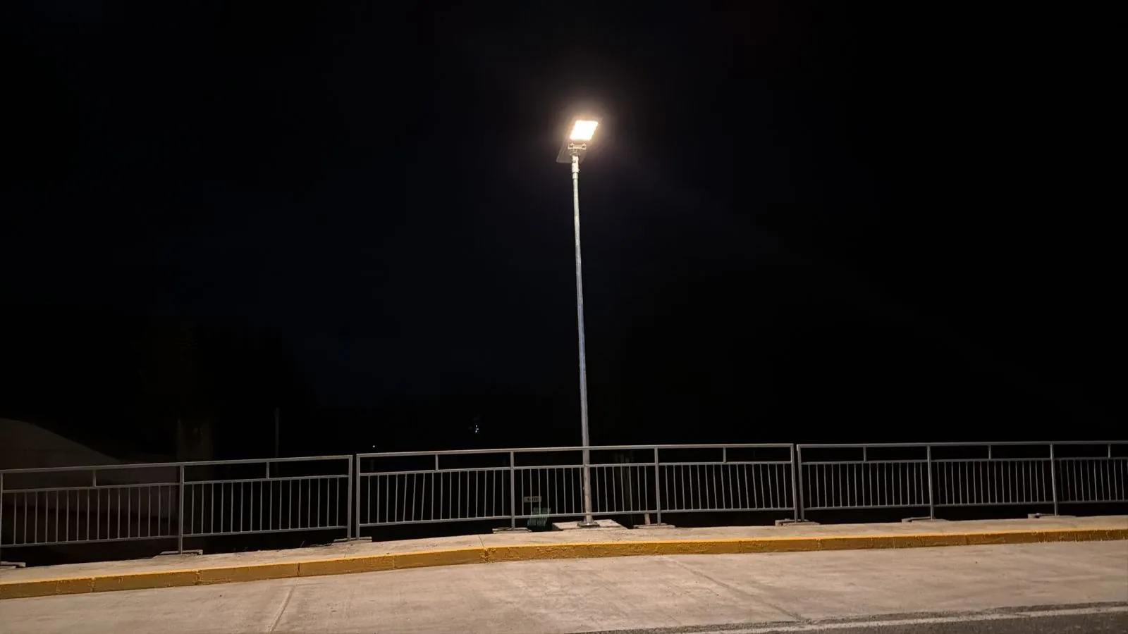
Route V-605 in Chile is the case we use when a client asks whether 30 W is enough for a rural road. The answer came from the photometric study and the worst-month sun at the site, not from the wattage: the road is lit, the uniformity passes and the battery carries the cloudy weeks.
Send the carriageway width, the speed limit and the pole height. We return a spacing calculation, a distribution type and a uniformity grid.
Request a road study